Today’s crash investigation professional makes use of all data sources at their disposal when reconstructing an incident. Most of the relevant data is collected with modern technology that combines mapping tools and photography.
Crews perform this type of data collection in short order, right at the scene. The goal is to clear wreckage quickly. However, mapping tools remain underutilized in gathering vehicle crush profile data. A a lofty expectation of time and personnel resources tends to scare people off.

Crush profile data measures and explains vehicle damage caused by collisions
A crush profile data set is essential for determining the maximum engagement between two vehicles, which contributes to finding the principal direction of force. It is also very useful for putting vehicles together in scaled diagrams and showing the sequence of the crash. Crush profiles help show the principle direction of force when two vehicles crash. When measuring crush on a vehicle by manual methods, the tools required to do the job can be inexpensive items like tape measures and simple levels.
Some manufacturers like Saker offer more expensive jigs or gauges, which can outline damage profiles. Something to consider is that you must purchase these devices in different sizes. Plus, each will have fixed intervals at which you can measure.
On top of that, the tool requires two operators to hold each end. Using one of these gauges, or even a classic tape measure, uses up more personnel resources that one hopes for. Typically, collection methods require you to record data by hand, opening up extra room for transcription errors.
People usually delineate crush by first setting up one axis across the extent of the damage, laterally. The next step is to take vehicle measurements along another axis using right angles. Much care keeps everything square and adds to the time of this method’s completion. In many cases like this, using manual tools can produce excessive error in the results, rendering the data useless to the investigator in the end. This is where high-tech comes in to play.
A much better method is to use a total station device, that measures horizontal and vertical angles, as well as distance to the target. These instruments do require a little bit of training but can be very simple to operate. A single operator can collect all the data necessary, making best use of the available manpower. The total station and software requires only a short setup. You can then collect data points along the line of crush on the vehicle in seconds. The means that the operator captures more data, at whatever interval they choose. No longer will their processes restrict to a fixed spacing.
Perhaps one of the biggest benefits of this method is the accuracy it provides. Using very simple precautions, the operator collects more precise data than manual methods. They perform the survey with very little risk of error. The investigator can have complete confidence in the results of a vehicle crush profile measured properly by a total station-type instrument.
Scanner technology from manufacturers such as Trimble and Leica can gather very precise crush data but the high cost, more complex procedure and sheer magnitude of data that must be processed makes them impractical for this application. Although slightly more expensive than the complicated jigs, simple total stations make short work out of what can be a difficult measurement scenario.

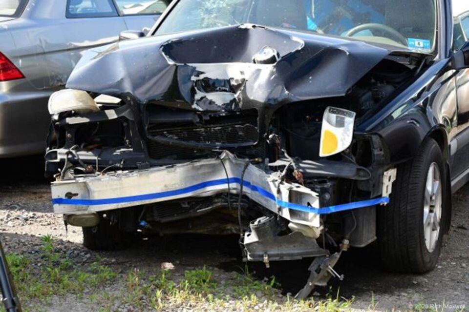
Blue tape visibly marks the point of maximum impact
The following case study demonstrates the benefits of our easy to operate, high-tech method for measuring vehicle crush profiles. The total station system in use is the TruPoint 300 product from Laser Tech, with their QuickMap3D flagship data collection app. This system is fully capable of recording all the important measurements for crush profile down to mm-level accuracy.
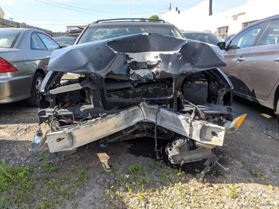
Access to the front of this vehicle where the damage in question occurred was already present. So, moving a vehicle to gain sight to the entire extent of the damage was not necessary.
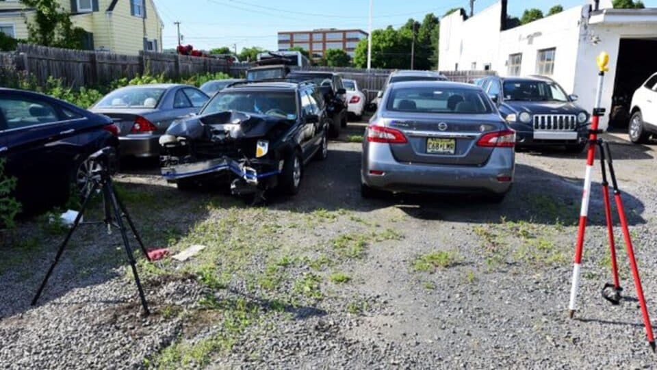
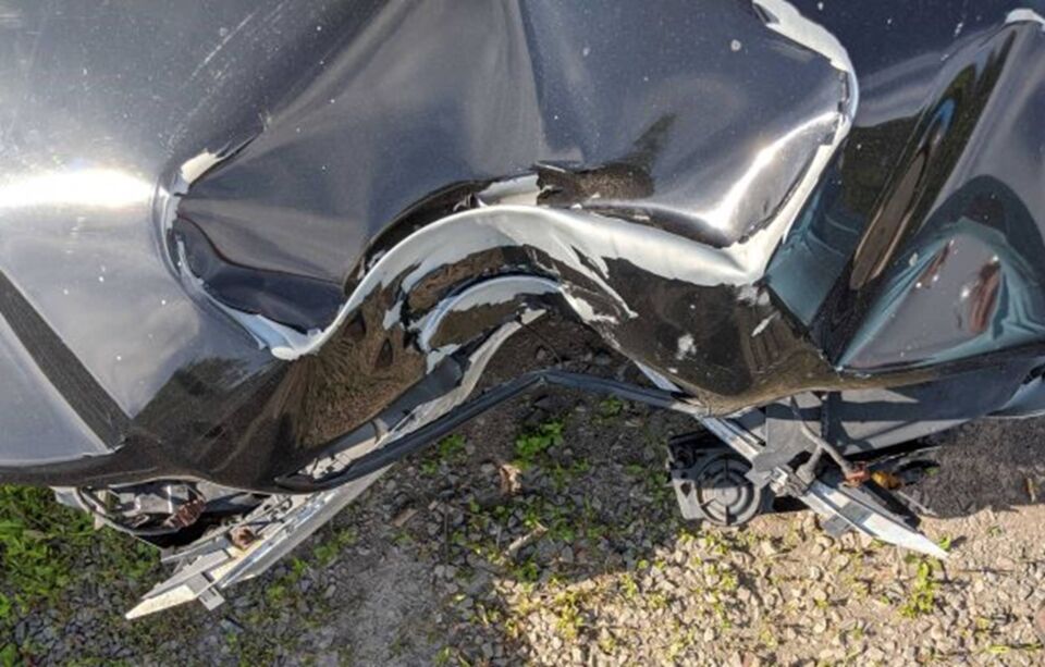
It is always best to visibly mark the point of maximum impact and construct a 2D plane of measurement across the boundary of the deformation. In this case we use a strip of blue tape. We position the total station at a comfortable distance from the vehicle. The operator may now walk between each without risk of bumping the instrument. We choose a spot where all the significant surfaces of the damage are clearly in line of sight.

A total station positions at a comfortable distance from the vehicle
Next, we establish a backsight point where we can reference the horizontal angle and begin our survey. We check this again when profiling is complete, for assurance in quality. In a matter of minutes, we can collect hundreds of data points, if necessary, with just one single operator. In this case, we take approximately 40 points along the marked 2D plane.
At this point, we can gather other critical points of reference on the vehicle. We want to collect all info that may be important to the crash investigator. This can include the corners of the body, but more importantly accounts for the axles, or center of the wheels, which are critical in when comparing the data to an exemplar vehicle. Use a target pole to accurately locate points of evidence that happen to be out of direct sight of the total station.
Let’ say that you need to measure damage on more than one side of a vehicle. Simply move the total station to another point and continue the survey of other crush areas. All the points will properly join in the data field and no stitching together of two data sets will be necessary.

Total station’s crush profile data
After checking the vehicle crush profile data for quality in the field, it can import directly into any popular CAD based (or other) diagramming software.
To the left, the raw data shows the crush profile, as well as the collected body and axle points. Next, we see a close up of the damage area with exemplar vehicle data overlaid on top of the crush, with the reference points at the axles accurately aligned.

Crush profile data answers questions for crash investigators
We can then calculate the crush measurement spacing based on the width of the damage, (2” in this case) and the corresponding displacement values, which we measure using a CAD program. This data feeds into the equations for determining speed from crush. We can then import the “to-scale” profile for use in the scaled diagram.
There is no doubt that a crush profile of a vehicle can be an extremely useful piece of the puzzle for the Crash Investigator. Today’s high-tech mapping method, using a simple total station system, makes the job of collecting this critical data quick and easy. Gather evidence with a minimum impact on valuable resources.
Then, watch the Detailed Vehicle Profile Crush Measurements Webinar to better understand how modern technology simplifies crush data collection.
Steve Colburn is the Applications Training Specialist at Laser Technology, Inc. Photos and case study data courtesy of: Rich Maxwell
Contact us today to see how Laser Tech’s products simplify crash and crime mapping.
Contact Us