Contact at Plant:
Steve Torres
SCADA Coordinator
719-556-2869
1300 S Queens Ave.
Pueblo, CO 81001
The City of Pueblo, Colorado is located at the confluence of the Arkansas River and Fountain Creek, 112 miles south of Denver, Colorado. With a population of over 160,000 people in its Metropolitan Statistical Area, it ranks ninth among Colorado cities.
The Test Site location is at the Nature & Wildlife Discovery Center, located in Rock Canyon along the banks of the Arkansas River. The mission of the Center is to provide unique experiences in education, conservation and recreation in environmental stewardship. In 2016, the Raptor Center admitted 372 raptors and released 100 back into the wild.
The test site selected at Pueblo Nature and Raptor Center is a Wet-Well (Lift Station). The wet well contains two digester pumps (Lead and Lag pumps) to maintain levels in the wet well from 2.2 feet to 3.2 feet. The current controller (DigiGauge 2300) uses a problematic Bubbler system (Differential Pressure) for level feedback used to control the pumps to maintain programmed levels. Since this site is designed to run autonomously, for redundancy, a mechanical float system is in place at over-alarm height and low-well alarm levels that will send an alarm to the office if they are detected.
The current controller in addition to the bubbler system has a 4-20mA input. A Laser Tech (LTI) TruSense® S330 will be used to replace the bubbler system for level measurement input in the water treatment plant.
There are 4 objectives for this beta site: 1) integration to existing standalone controllers, 2) ease of setup, 3) sensor data collection for later evaluation and 4) environmental operation.
The reason for this system is to collect wastewater from the park and park restaurant, then lift the wastewater to be processed. Current system components are two digester pumps, DigiGage controller (Bubbler system feedback), remote cellular system, and a mechanical float system as a backup level control.
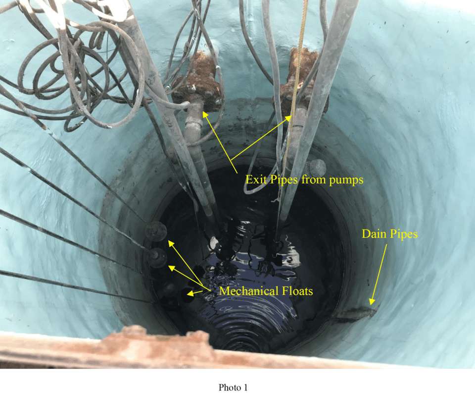
The Wet-Well dimensions are approximately 8 feet in diameter and 10.5 feet deep. There are three pipes that drain into the Wet-Well from the park’s facilities. See photo 1
Water treatment plant is used to test a Laser Tech (LTI) TruSense S330
The objective is to allow the wet well to fill to a predefined height and then lift the wastewater from the wet well to be processed. To prevent the pump(s) from running dry, when the level gets down to a predefined level the pump(s) should turn off. During normal pump-down operations, only one pump (Lead pump) is required. The second pump (Lag Pump) is used during high-demand effluence filling.
If the system moves out of bounds of the control levels for any reason, there are Over and Under alarm points. Once a critical alarm level has been detected, the cellular system will phone home to alert that a critical level has been met.
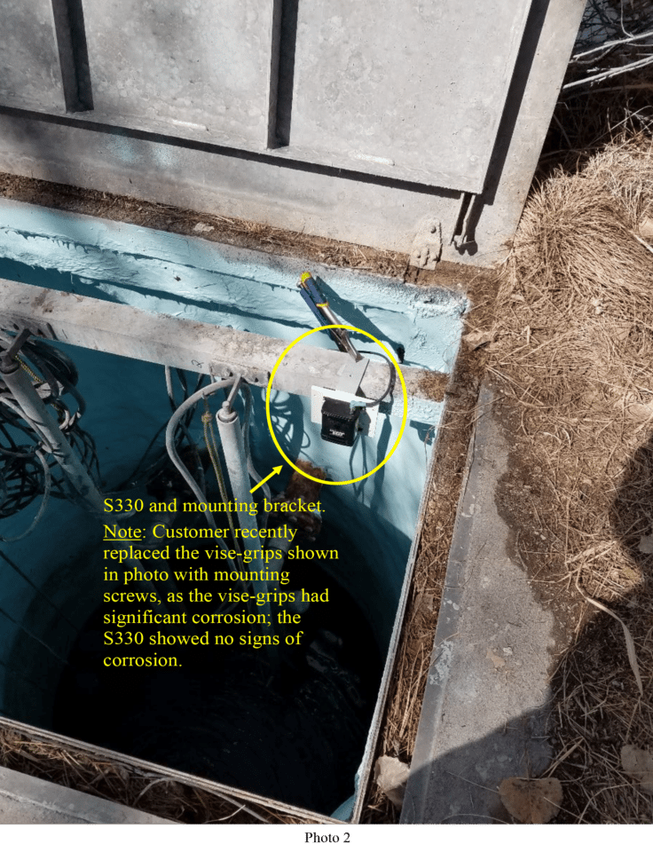
To integrate the S330 into the system a bracket was made for mounting the sensor in the Wet-Well on an existing angle iron support (See photo 2). The shielded cable that comes with the S330 was used to connect the sensor to the control panel via an existing pipe leading from the Wet-Well into the control panel. See Appendix A for a detailed setup.
Setup was made quick and easy using the 4-20mA Setup software provided by Laser Technology.
The next step was to reprogram the DigiGage to use the 4-20mA loop input to replace the bubbler system input.
After the sensor and DigiGage were configured, a data collector was attached to capture the RS-232 measurement data for later evaluation.
The final step, after verification of the system operation, was to allow the DigiGage to control the system. The system has been currently running since March 5, 2019, and as of the printing of this paper in October 2019, has continued to run without any alarms of failures.
Laser Tech (LTI) TruSense S330 installed at a water treatment plant
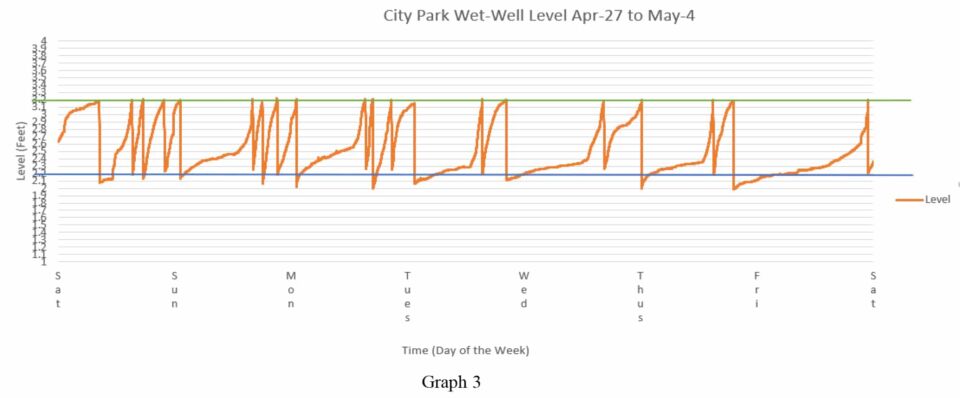
The below graph’s (Graph 1) timeline is from March 15th through June 25th.
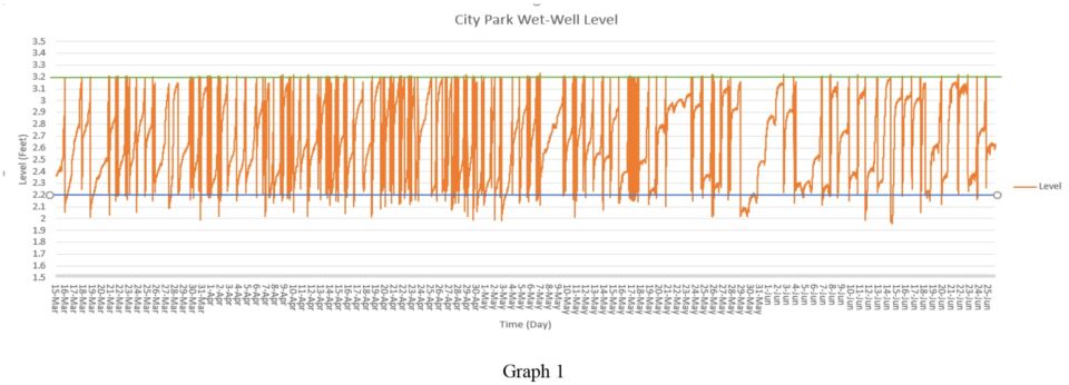
The green horizontal line is the lead pump turn-on point (3.2 feet). The blue horizontal line is the lead/lag pump turn-off point (2.2 feet). The orange line is the distance output of the
S330.
First two things to note is at no time the system was out of control (Alarm point met) and only the lead pump was used during this time period. Inflow into the Wet-Well is controlled by park usage and outflow (pump-down) is controlled by the Lead/Lag pump volume. Since the difference in inflow is much less than outflow, the outflow time does not noticeably vary from pump-down cycle to pump-down cycle. The below graph shows one pump-down cycle (Graph 2).
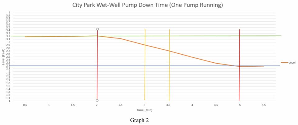
The green line represents the lead pump turn-on and the blue horizontal line represents the pump turn-off . Between red vertical lines is one period the pump is on which is about 3 minutes (Pump-down from 3.2 feet to 2.2 feet = one pump-down cycle). Where the yellow vertical line intersects the orange measurement line defines one 30-second interval. The level rate of change is about .2 feet every 30 seconds. During setup, the 4-20 loop update was set to a 30-second update interval per the customer’s request.
In both Graphs 1 and 3, the pump turn-on points (green horizontal line) are very repeatable, and the pump turn-off points (blue horizontal line) vary up to .2 of a foot. This is directly attributed to the slow rise time and fast fall time in relation to the loop update period. Since the rise time is slow, in 30 seconds the level does not change much. During a pump-down, a 30-second delay can equate up to a .2 foot variance in levels before the pump turn-off.
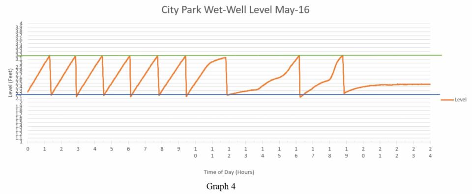
A closer look at May 16th was a high usage day. Graph 4 shows the day starting with a fast fill rate from 12 am to 7 pm, followed by a slow fill rate.
The sensor was installed about 6” under an aluminum lid that covered the wet well. It is exposed to Hydrogen Sulfide (H2S) gas which is very corrosive.
During the testing, the sensor was exposed to temperatures ranging from about 32° F to 105°. This is based on the open-air temperatures during the testing period. After continued operation from March 10 to August , the sensor showed no signs of corrosion and continues to work fine as of the printing of this document in October 2019.
This beta testing has proven the S330 is a very capable non-contact level sensor in an enclosed environment. The best advantages the sensor has are ease of setup, ease of maintenance with minimal downtime, and ability to work in corrosive liquids environments.
In the wastewater industry, the S330 would integrate well since it is non-contact and not subject to failure in contaminated water like Bubbler systems or pressure sensors.
In conclusion, the S330 has proven that the sensor can hold up in a corrosive environment and provide to be a reliable level measurement sensor for information and/or control of a
system. The sensor also proved to be very repeatable over time.
Leveraging the 4-20mA loop, the S330 can directly replace aging unreliable measurement systems currently using the 4-20mA communication loop.